画一些三角形(Games101作业1-2)

免责声明:此文章为记录自主学习图形学机制而留,并没有提交到BSS论坛,请勿直接复制粘贴,后果自负。

HomeWork1:MVP矩阵

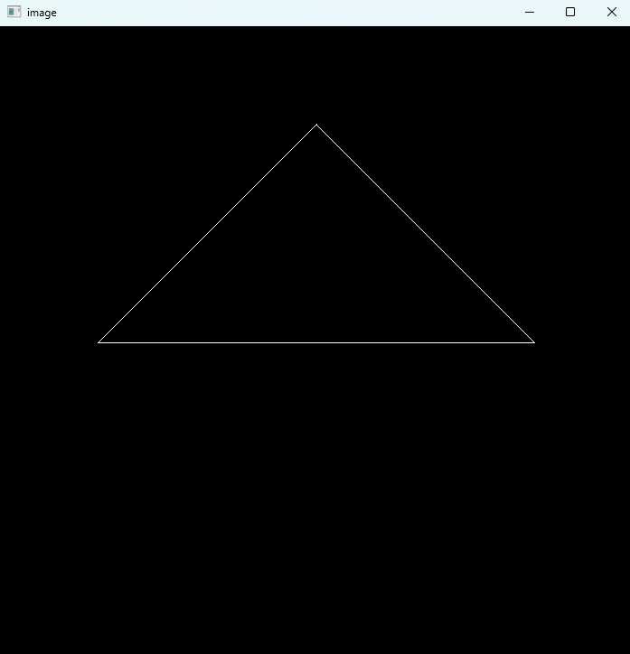
作业的最终效果如下:就是让我们画一个三角形,作业包已经完成了大部分的内容,所以我们最后只用填入模型的变换矩阵M和投影矩阵P

alt text

什么是MVP矩阵?

在计算机图形学中,我们用向量表示一个点,用向量表示一个虚拟世界,而最后这些模型有些会进入我们的屏幕而有的不会,这就是经历了mvp矩阵变换的结果。 顾名思义:m代表模型矩阵,用来表示模型的空间位置;v代表观测变换,表示我们用照相机产生的一个视野,为了方便实现,挪动相机实际上就是挪动整个世界而相机不动;P代表投影,类似于最后成像的方式

仿射变换

实际上M和V矩阵都是让世界物体做仿射变换,那什么是仿射变换? 简单来说就是平移+旋转+放缩三种变换的统称,我们用矩阵表示就是:

$$\begin{bmatrix}x' \\y' \\z' \\1\end{bmatrix}=\begin{bmatrix}R & \mathbf{t} \\\mathbf{0}^T & 1\end{bmatrix}\begin{bmatrix}x \\y \\z \\1\end{bmatrix}$$

其中$R$表示旋转/缩放的部分,$t_x,t_y,t_z$是平移。 为了更直观,我们把三种基本变换拆开写: 平移矩阵:

$$ T(\Delta x,\Delta y,\Delta z)= \begin{bmatrix} 1 & 0 & 0 & \Delta x \\ 0 & 1 & 0 & \Delta y \\ 0 & 0 & 1 & \Delta z \\ 0 & 0 & 0 & 1 \end{bmatrix} $$

绕$z$轴旋转:

$$ R_z(\theta)= \begin{bmatrix} \cos\theta & -\sin\theta & 0 & 0 \\ \sin\theta & \cos\theta & 0 & 0 \\ 0 & 0 & 1 & 0 \\ 0 & 0 & 0 & 1 \end{bmatrix} $$

绕$x$轴旋转:

$$ R_x(\theta)= \begin{bmatrix} 1 & 0 & 0 & 0 \\ 0 & \cos\theta & -\sin\theta & 0 \\ 0 & \sin\theta & \cos\theta & 0 \\ 0 & 0 & 0 & 1 \end{bmatrix} $$

绕$y$轴旋转:

$$ R_y(\theta)= \begin{bmatrix} \cos\theta & 0 & \sin\theta & 0 \\ 0 & 1 & 0 & 0 \\ -\sin\theta & 0 & \cos\theta & 0 \\ 0 & 0 & 0 & 1 \end{bmatrix} $$

实际上还有绕任意轴旋转的矩阵(罗德里格斯旋转公式):

$$ R_{\mathbf{u}}(\theta)=I\,c+(1-c)\,\mathbf{u}\mathbf{u}^T+s\,[\mathbf{u}]_\times $$

其中$\mathbf{u}=(u_x,u_y,u_z)$为单位向量,$c=\cos\theta,s=\sin\theta$,

$$ [\mathbf{u}]_\times= \begin{bmatrix} 0 & -u_z & u_y \\ u_z & 0 & -u_x \\ -u_y & u_x & 0 \end{bmatrix} $$

缩放矩阵:

$$ S(s_x,s_y,s_z)= \begin{bmatrix} s_x & 0 & 0 & 0 \\ 0 & s_y & 0 & 0 \\ 0 & 0 & s_z & 0 \\ 0 & 0 & 0 & 1 \end{bmatrix} $$

这三种矩阵按顺序相乘就是模型矩阵$M$。注意矩阵相乘是有顺序的,例如先旋转再平移和先平移再旋转效果不一样。

观测矩阵V

将三维的点集由世界坐标变换为相机坐标; 相机有如下几种属性:位置$\vec{e}$ ,视线方向$\hat{g}$ ,向上方向$\hat{t}$ (假设与视线方向垂直) 我们将原坐标系变换为相机坐标系,并符合如下规则:相机在原点、向上方向为 $y+$ ,视线方向为 $z-$ ($x+$ is $\hat{g}\times\hat{t}$, $y+$ is $\hat{t}$, $z+$ is $-\hat{g}$); 假设变换矩阵为 $M_{view}$ ,考虑其的形式($M_{view}=R_{view}T_{view}$):首先需要将相机点移到原点($T_{view}=T(-\vec{e})$),再进行坐标轴变换; 考虑 $R_{view}^{-1}$ 即从相机坐标系变换回原坐标系:参考

$$ R_{view}^{-1}= \begin{bmatrix} x_{\hat{g}\times\hat{t}} & x_{\hat{t}} & x_{-\hat{g}} & 0 \\ y_{\hat{g}\times\hat{t}} & y_{\hat{t}} & y_{-\hat{g}} & 0 \\ z_{\hat{g}\times\hat{t}} & z_{\hat{t}} & z_{-\hat{g}} & 0 \\ 0 & 0 & 0 & 1 \end{bmatrix} $$

得:

$$ R_{view}= \begin{bmatrix} x_{\hat{g}\times\hat{t}} & x_{\hat{t}} & x_{-\hat{g}} & 0 \\ y_{\hat{g}\times\hat{t}} & y_{\hat{t}} & y_{-\hat{g}} & 0 \\ z_{\hat{g}\times\hat{t}} & z_{\hat{t}} & z_{-\hat{g}} & 0 \\ 0 & 0 & 0 & 1 \end{bmatrix} $$

投影矩阵P

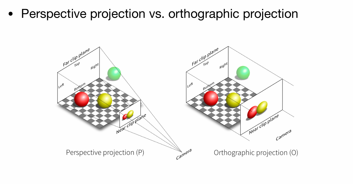
投影的作用是把3D的物体压到2D平面上。可以分成两步:透视到正交,再做正交投影。 具体来说:正交投影就是把将$z$坐标写为0之后把$(-\infty,+\infty)^2$的物体写入$[-1,+1]^3$的标准立方体中,投影出来的效果不符合现实世界观察近大远小的规律
而透视投影就是模拟真实世界观测的效果(近大远小,平行线看着不平行)具体做法就是将一个以原点为锥点的截锥体变换成立方体,再进行正交投影,就完成了透视投影的过程. alt text

  1. 透视到正交的变换: $$ M_{persp\to ortho}= \begin{bmatrix} z_{near} & 0 & 0 & 0 \\ 0 & z_{near} & 0 & 0 \\ 0 & 0 & z_{near}+z_{far} & -z_{near}z_{far} \\ 0 & 0 & 1 & 0 \end{bmatrix} $$
  2. 正交投影把视锥体挤到标准立方体里。设视角为$\text{fov}$,宽高比为$\text{aspect}$,近远平面为$z_{near},z_{far}$, 则上/下/左/右边界为: $$ t=|z_{near}|\tan\left(\frac{\text{fov}}{2}\right),\quad b=-t,\quad r=t\cdot \text{aspect},\quad l=-r $$ 正交投影矩阵: $$ M_{ortho}= \begin{bmatrix} \frac{2}{r-l} & 0 & 0 & -\frac{r+l}{r-l} \\ 0 & \frac{2}{t-b} & 0 & -\frac{t+b}{t-b} \\ 0 & 0 & \frac{2}{z_{near}-z_{far}} & -\frac{z_{near}+z_{far}}{z_{near}-z_{far}} \\ 0 & 0 & 0 & 1 \end{bmatrix} $$ 最终的投影矩阵就是: $$ P=M_{ortho}M_{persp\to ortho} $$

MVP合成

在代码里我们把三个矩阵按顺序乘起来,就是:

$$ MVP=P\,V\,M $$

最后顶点经过$MVP$变换,再做一次齐次除法(除以$w$)就可以得到屏幕上的点了。 在了解这些前置知识之后,我们就可以开始作业1了!
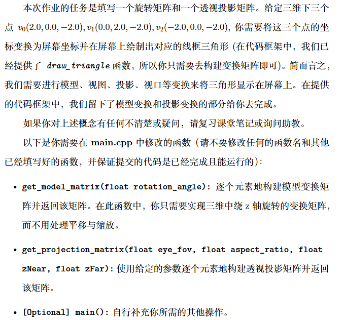
alt text
发现作业的基础项只需要我们完成两个函数get_model_matrixget_projection_matrix这两个函数一个对应模型的位移,另一个则对应透视投影,我们直接将上文中的公式代入,得到:
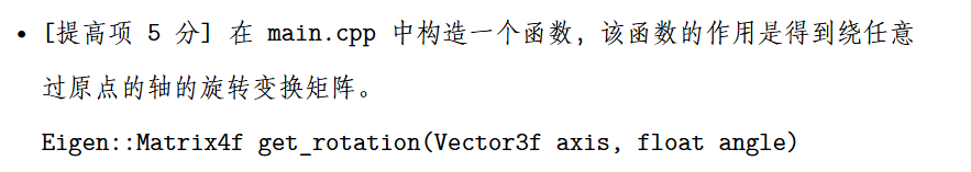
 1
 2
 3
 4
 5
 6
 7
 8
 9
10
11
12
13
14
15
16
17
18
19
20
21
22
23
24
25
26
27
28
29
30
31
32
33
34
35
36
37
38
39
40
41
42
43
44
45
46
47
48
49
50
Eigen::Matrix4f get_model_matrix(float rotation_angle)
{
    using std::cos,std::sin;
    Eigen::Matrix4f model = Eigen::Matrix4f::Identity();

    // TODO: Implement this function
    // Create the model matrix for rotating the triangle around the Z axis.
    // Then return it.
    float rta=rotation_angle/180.0*MY_PI;
    transformer<<cos(rta),-sin(rta),0,0,
                 sin(rta),cos(rta), 0,0,
                 0,       0,        1,0,
                 0,       0,        0,1;
    
    model=transformer*model;
    return model;
}
Eigen::Matrix4f get_projection_matrix(float eye_fov, float aspect_ratio, float zNear, float zFar)
{
    Eigen::Matrix4f projection = Eigen::Matrix4f::Identity();

    // 注意:第四行第三列改为-1,适配右手系相机看向-Z
    Eigen::Matrix4f M_persp;
    M_persp <<
        zNear, 0, 0, 0,
        0, zNear, 0, 0,
        0, 0, zNear + zFar, -zFar * zNear,
        0, 0, -1, 0; 

    float half_fov = 0.5f * eye_fov * MY_PI / 180.0f;
    float t = zNear * std::tan(half_fov); 
    float r = t * aspect_ratio;            
    float b = -t;                        
    float l = -r;                       

    // 注意 Z 轴:n = -zNear, f = -zFar
    float n = -zNear;
    float f = -zFar;

    Eigen::Matrix4f M_ortho;
    M_ortho <<
        2/(r-l), 0,       0,       -(r+l)/(r-l),
        0,       2/(t-b), 0,       -(t+b)/(t-b),
        0,       0,       2/(n-f), -(n+f)/(n-f),
        0,       0,       0,       1;

    projection = M_ortho * M_persp;

    return projection;
}

关于提高项:

alt text
其实就是运用上文的罗德里格斯旋转公式,我们将公式代入得到:

 1
 2
 3
 4
 5
 6
 7
 8
 9
10
11
12
13
14
15
16
17
18
19
20
21
22
23
24
25
26
27
28
29
30
Eigen::Matrix4f get_rotation(Eigen::Vector3f axis, float angle) {

    Eigen::Matrix4f ans = Eigen::Matrix4f::Identity();
    Eigen::Matrix3f one;
    one << 1,0,0, 
           0,1,0, 
           0,0,1;

    float alpha = angle / 180 * MY_PI;
    float cs = cos(alpha), sn = sin(alpha);
    float x = axis[0], y = axis[1], z = axis[2];
    Eigen::Matrix3f cross;
    cross << 0,-z,y, 
             z,0,-x, 
             -y,x,0;

    Eigen::Matrix3f tmp = cs*one + (1-cs)*axis*axis.transpose() + sn*cross;

    for(int i = 0;i < 4;i ++) {
        for(int j = 0;j < 4;j ++) {
            if(i < 3 && j < 3)
                ans(i,j) = tmp(i,j);
            else if(i == 3 && j == 3)
                ans(i,j) = 1;
            else
                ans(i,j) = 0;
        }
    }
    return ans;
}

调用也很简单:我们只需要:Eigen::Matrix4f transformer=get_rotation(Eigen::Vector3f(0,0,1),rotation_angle);就可以实现绕z轴旋转

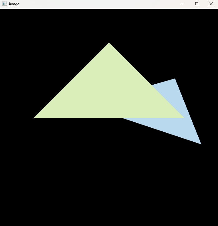
Homework2:采样和z-buffering

第二个作业的最终效果如下图:

alt text
在上一个作业中,我们只完成了MVP矩阵,让这些图形全都在一个$[-1,1]^3$的标准立方体中,但实际上,我们最终是要把图形打到一个二维平面上,而采样就是在完成这一过程。 我们知道,屏幕实际上就是一些像素整齐的排列成矩阵,我们把像素排列抽象成一个的矩阵
alt text

视口变换(Viewport Transformation)

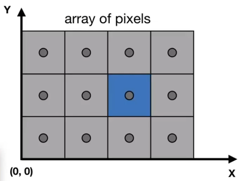
经过MVP变换后,顶点位于$[-1,1]^3$的立方体中。为了将这些坐标映射到实际的屏幕像素坐标,我们需要进行视口变换。 视口变换将NDC坐标映射到屏幕坐标系,其中屏幕左下角为$(0,0)$,右上角为$(width, height)$。视口矩阵$M_{viewport}$定义为:

$$ M_{viewport} = \begin{bmatrix} \frac{w}{2} & 0 & 0 & \frac{w}{2} + x \\ 0 & \frac{h}{2} & 0 & \frac{h}{2} + y \\ 0 & 0 & \frac{1}{2} & \frac{1}{2} \\ 0 & 0 & 0 & 1 \end{bmatrix} $$

其中:

  • $w$ 是视口的宽度
  • $h$ 是视口的高度
  • $x, y$ 是视口左下角在屏幕上的坐标(通常为0) 这样,正方体中的点$(x_{ndc}, y_{ndc}, z_{ndc})$经过视口变换后变为屏幕坐标$(x_{screen}, y_{screen}, z_{screen})$。

采样和光栅化

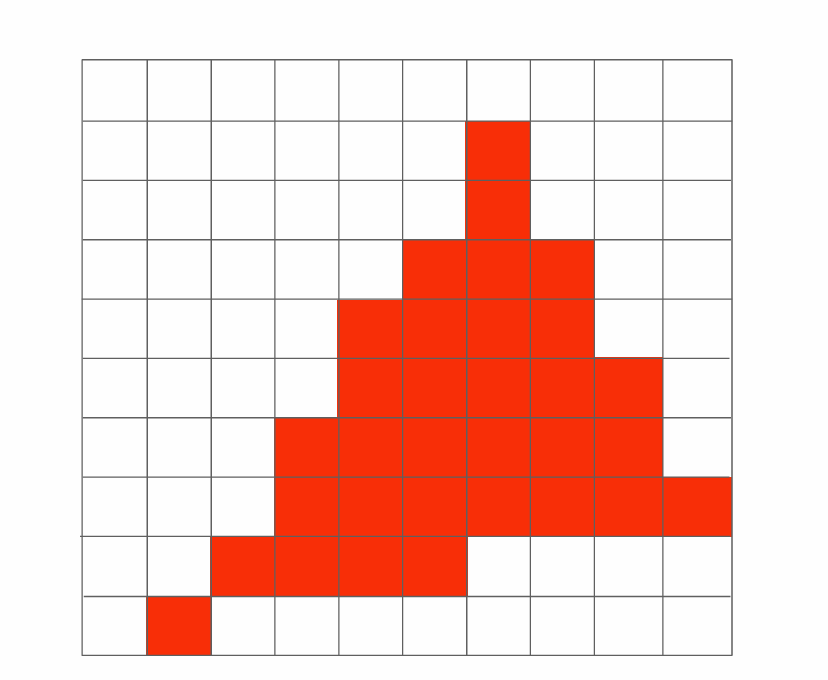
采样是将连续的几何体转换为离散的像素的过程。这个过程称为光栅化。

基本步骤

  1. 边界框计算:为每个三角形计算其在屏幕上的轴对齐边界框(Axis-Aligned Bounding Box, AABB),以减少需要检查的像素数量。

  2. 像素采样:对于边界框内的每个像素,检查像素中心是否位于三角形内部。课里面教的是直接顺时针的方向和三角形里的每个点进行叉乘,若全部同号则在三角形内部,但是不太好处理叉积=0的情况,所以在这里介绍使用重心坐标来判断:

    • 三角形三个顶点为$\mathbf{v}_0, \mathbf{v}_1, \mathbf{v}_2$
    • 对于像素中心点$\mathbf{p}$,计算重心坐标$(\alpha, \beta, \gamma)$
    • 如果$\alpha \geq 0, \beta \geq 0, \gamma \geq 0$,则点在三角形内

    重心坐标可以通过叉积计算:

    $$ \alpha = \frac{ (\mathbf{v}_1 - \mathbf{v}_0) \times (\mathbf{p} - \mathbf{v}_0) }{ (\mathbf{v}_1 - \mathbf{v}_0) \times (\mathbf{v}_2 - \mathbf{v}_0) } $$

    我们可以用同样的方式计算$\beta, \gamma$。

  3. 属性插值:对于在三角形内的像素,使用重心坐标插值顶点属性,如颜色、纹理坐标等。

  4. 深度插值:同样使用重心坐标插值深度值,用于z-buffering。

Z-Buffering

Z-Buffering是一种解决可见性问题的算法,用于确定哪个像素在前。

  • 维护一个深度缓冲区,大小与屏幕像素相同,初始值为无穷大(表示最远)。
  • 对于每个像素,如果其插值深度小于缓冲区中的值,则更新缓冲区并绘制该像素。
  • 这样确保了近的物体覆盖远的物体。

反走样

如果我们直接按照上述的朴素算法渲染图形,最后打在画面上的结果就会这样:

alt text
这明显不是我们想要的效果!因此我们引入反走样 反走样(Anti-Aliasing,AA)用于减弱光栅化后出现的锯齿。常见策略有三类:

  • 超采样(SSAA):对每个像素做多次子像素采样并平均,简单但计算量大;
  • 多重采样(MSAA):对深度/覆盖做多样本采样、对颜色按片元计算,降低开销;
  • 屏幕空间后处理(FXAA/SMAA):基于像素图像做边缘检测与滤波,速度快但可能模糊细节。
  • 时域抗锯齿(TAA):类似于在时域上进行多重采样。

简单2×2SSAA

对每个像素采样 4 个子样本,常用位置(以像素左下为 (0,0))为: $(0.25,0.25),(0.75,0.25),(0.25,0.75),(0.75,0.75)$。

MSAA与后处理

  • MSAA:为每像素维护 N 个样本的深度/覆盖,着色器通常按片元执行一次,覆盖到被占据的样本;
  • FXAA/SMAA:基于最终图像的边缘检测与滤波,代价低、易集成,但属于近似方法,会影响锐利细节。 了解这些前置知识之后,我们来到作业2:
    alt text
    我们直接实现提高项:实现一个2x2的ssaa:
    alt text
    我们先实现判断一个点是否在三角形内部的函数insideTriangle参考上文,我们使用重心坐标法实现:
 1
 2
 3
 4
 5
 6
 7
 8
 9
10
11
12
13
14
15
16
17
18
19
20
Eigen::Vector3f computeBarycentric(float x, float y, const Vector3f *v) {
    auto area2 = [](const Vector3f &a, const Vector3f &b, const Vector3f &c) {
        return (b.x()-a.x()) * (c.y()-a.y()) - (b.y()-a.y()) * (c.x()-a.x());
    };

    Vector3f P(x, y, 0);
    float A = area2(v[0], v[1], v[2]);
    if (std::fabs(A) < 1e-8f) return Eigen::Vector3f(-1, -1, -1); 

    float alpha = area2(P, v[1], v[2]) / A;
    float beta  = area2(P, v[2], v[0]) / A;
    float gamma = 1.0f - alpha - beta; 
    return Eigen::Vector3f(alpha, beta, gamma);
}
static bool insideTriangle(float x, float y, const Vector3f *_v)
{
    Eigen::Vector3f bary = computeBarycentric(x, y, _v);
    if (bary.x() < -0.5f) return false; 
    return (bary.x() >= -0.0000001 && bary.y() >= -0.0000001 && bary.z() >= -0.0000001);
}

在正式实现光栅化之前,我们要先修改hpp的对象结构,我们需要额外的维护一个std::vector< std::vector<std::pair<float, Eigen::Vector3f>> > depColor来维护深度测试当前最前面的颜色,为了代码美观,我还额外定义了一个N=2来表示当前ssaa的分割数 参照上文,我们要先判断这个三角形的AABB包围盒来减少像素计算数量,然后再对内部进行细分,每个点进行一次采样和深度测试,更新depcolor的值,在做完ssaa之后,记得调用set_pixel函数来设置像素值

 1
 2
 3
 4
 5
 6
 7
 8
 9
10
11
12
13
14
15
16
17
18
19
20
21
22
23
24
25
26
27
28
29
30
31
32
33
34
35
36
37
38
39
40
41
42
43
44
45
46
47
48
49
50
51
52
53
54
55
56
57
58
59
60
61
62
63
64
65
66
67
void rst::rasterizer::rasterize_triangle(const Triangle& t) {
    auto v = t.toVector4();
    
    // TODO : Find out the bounding box of current triangle.
    // iterate through the pixel and find if the current pixel is inside the triangle

    // If so, use the following code to get the interpolated z value.
    //auto[alpha, beta, gamma] = computeBarycentric2D(x, y, t.v);
    //float w_reciprocal = 1.0/(alpha / v[0].w() + beta / v[1].w() + gamma / v[2].w());
    //float z_interpolated = alpha * v[0].z() / v[0].w() + beta * v[1].z() / v[1].w() + gamma * v[2].z() / v[2].w();
    //z_interpolated *= w_reciprocal;

    // TODO : set the current pixel (use the set_pixel function) to the color of the triangle (use getColor function) if it should be painted.

    double minX, maxX, minY, maxY;
    minX = maxX = v[0][0];
    minY = maxY = v[0][1];  
    for(int i = 0;i < 3;i ++) {
        minX = std::min(minX, (double)v[i][0]);
        maxX = std::max(maxX, (double)v[i][0]);
        
        minY = std::min(minY, (double)v[i][1]);
        maxY = std::max(maxY, (double)v[i][1]);
    }

    int ixMin = std::max(0, (int)minX);
    int ixMax = std::min(width - 1, (int)maxX);
    int iyMin = std::max(0, (int)minY);
    int iyMax = std::min(height - 1, (int)maxY);

    for(int ix = ixMin; ix <= ixMax; ix ++) {
        for(int iy = iyMin; iy <= iyMax; iy ++) {
            int id = 0;
            for(int i = 0;i < N;i ++) {
                for(int j = 0;j < N;j ++) {
                    float d = 1.0 / (2 * N);
                    float x = ix + 2 * d * i + d, y = iy + 2 * d * j + d;
                    if(insideTriangle(x, y, t.v)) {
                        auto[alpha, beta, gamma] = computeBarycentric2D(x, y, t.v);
                        float w_reciprocal = 1.0/(alpha / v[0].w() + beta / v[1].w() + gamma / v[2].w());
                        float z_interpolated = alpha * v[0].z() / v[0].w() + beta * v[1].z() / v[1].w() + gamma * v[2].z() / v[2].w();
                        z_interpolated *= w_reciprocal;

                        if(depColor[get_index(ix, iy)][id].first > z_interpolated) {
                            depColor[get_index(ix, iy)][id].first = z_interpolated;
                            depColor[get_index(ix, iy)][id].second = t.getColor();
                        }
                    }

                    id ++;
                }
            }

            Eigen::Vector3f color = {0, 0, 0};
            id = 0;
            for(int i = 0;i < N;i ++) {
                for(int j = 0;j < N;j ++) {
                    color += depColor[get_index(ix, iy)][id].second;
                    id ++;
                }
            }

            color /= N*N;
            set_pixel(Eigen::Vector3f(ix, iy, 1), color);
        }
    }
}

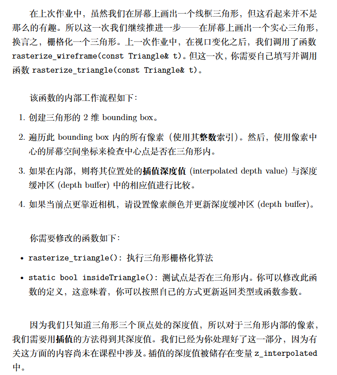
致此,我们把3D图形的变换以及把图形打到屏幕上的过程走通了一遍,但这还不是完整的渲染管线,实际上,我们一直没有考虑到着色的情况,这也是接下来的课程和作业所关注的

Licensed under CC BY-NC-SA 4.0
使用 Hugo 构建
主题 StackJimmy 设计